前回は、bootloaderの仕組みなどを12F1822ベースで記載しましたが、他にも使用したかった16F1828/9にもbootloaderを対応させたました。
基本的なところは以下のPICは一緒ですので、他もついでに対応しました。
12F1822
16F1823
16F1824
16F1825
16F1828
16F1829
違いは、UARTのTX/RXのピンアサインとFLASHメモリーの大きさ、WRITE/ERASE FLASH Blockのサイズです。
その部分をデバイスによって場合分けしただけです。
以下は、ピンアサイン
;
;                  12F1822
;                  ---O---
;          Vdd   -|1     8|-   GND
; RA5/           -|2     7|-   TX   /RA0
; RA4/           -|3     6|-   RX   /RA1
; RA3/    MCLR   -|4     5|-        /RA2
;                  -------

;                  12F1823/4/5
;                  ---O---
;          Vdd   -|1    14|-   GND
; RA5/           -|2    13|-   TX   /RA0
; RA4/           -|3    12|-   RX   /RA1
; RA3/    MCLR   -|4    11|-        /RA2
; RC5/           -|5    10|-        /RC0
; RC4/           -|6     9|-        /RC1
; RC3/           -|7     8|-        /RC2
;                  -------

;
;                  16F1828/9
;                  ---O---
;          Vdd   -|1    20|-   GND
;                -|2    19|-
; 	         -|3    18|-
;                -|4    17|-
;         MCLR   -|5    16|-
; 	         -|6    15|-
; 	         -|7    14|-
; 	         -|8    13|-
; 		 -|9    12|-   RX/RB5
;        RB5/TX  -|10   11|-
;                  -------
TX/RXのポートをデジタルにする
; Port-x all pins are Digital I/O (for setting TX and RX as digital pins)
#ifdef __12F1822
	BANKSEL	ANSELA
	clrf	ANSELA
endif
#ifdef __16F1823
	BANKSEL	ANSELA
	clrf	ANSELA
endif
#ifdef __16F1824
	BANKSEL	ANSELA
	clrf	ANSELA
endif
#ifdef __16F1825
	BANKSEL	ANSELA
	clrf	ANSELA
endif
#ifdef __16F1828
    BANKSEL ANSELB
    clrf    ANSELB
endif
#ifdef __16F1829
    BANKSEL ANSELB
    clrf    ANSELB
endif
RXピンを入力にする
; RX pin should be set input
#ifdef __12F1822
	BANKSEL TRISA
	movlw   B'00000010'
        movwf   TRISA
endif
#ifdef __16F1823
	BANKSEL TRISA
	movlw   B'00000010'
        movwf   TRISA
endif
#ifdef __16F1824
	BANKSEL TRISA
	movlw   B'00000010'
        movwf   TRISA
endif
#ifdef __16F1825
	BANKSEL TRISA
	movlw   B'00000010'
        movwf   TRISA
endif
#ifdef __16F1828
	BANKSEL TRISB
	movlw   B'00100000'
        movwf   TRISB
endif
#ifdef __16F1829
	BANKSEL TRISB
	movlw   B'00100000'
        movwf   TRISB
endif
redo loopをするしない(これはFLASH WRITE/ERASE BLOCKサイズできまります)
WriteLoopNext:
    incf    EEADRL,F                    ; Assume still loading latches, increment Prog-memory address pointer
    decf    BytesInBlock,F
    decfsz  BytesInBlock,F
    goto    WriteLoop

    call    WriteMemBlock
    decfsz  BlockCount,F

#ifdef __12F1822
	goto    RedoLoop
endif
#ifdef __16F1823
	goto    RedoLoop
endif
#ifdef __16F1824
	goto	WriteLoop
endif
#ifdef __16F1825
	goto	WriteLoop
endif
#ifdef __16F1828
	goto	WriteLoop
endif
#ifdef __16F1829
	goto	WriteLoop
endif
	return

RedoLoop:
    movlw   0x20			; This is the number of BYTES inside one write-block (16words = 32bytes for 12F1822)
    movwf   BytesInBlock
    incf	EEADRL, F
    ;goto	WriteLoop		; Should go to ErasePgmMem again ...to erase more 16 word(32byte) block.
    goto	ErasePgmMem
以下からダウンロード可能です。
12F1822-16F182x_bootloader_af (56.69kB)
16F1823/4/5は、手持ちがありませんでしたので、試せてません。
うまくいったという方はコメントもらえたらと思います。

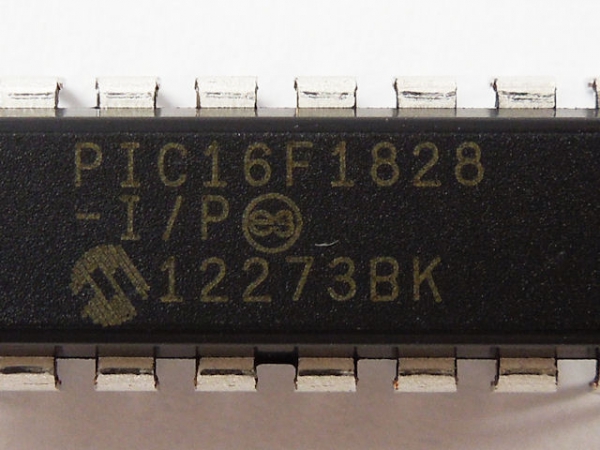

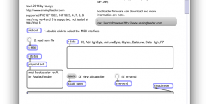
Serial Bootloader AN1310 v1.05r で PIC16LF1829 との接続に成功しました。
ソースファイル(PIC16 Bootloader)の変更は preprocess.inc の26行目に次の20行を挿入するだけです。
#ifdef __16LF1829
#define USE_MAX_INTOSC ; (bootconfig.inc でも設定可)
#define USE_PLL ; (bootconfig.inc でも設定可)
__CONFIG _CONFIG1, 0x3fff & _FCMEN_ON & _IESO_OFF & _CLKOUTEN_OFF & _BOREN_OFF & _CPD_OFF & _CP_OFF & _MCLRE_ON & _PWRTE_ON & _WDTE_OFF & _FOSC_INTOSC
__CONFIG _CONFIG2, 0x3fff & _LVP_ON & _BORV_LO & _STVREN_ON & _PLLEN_OFF & _WRT_OFF
; (以下は__16F1828と同じ)
#ifdef USE_ALTERNATE_PINS
; UART option for TX/RC4 and RX/RC5 pins.
#define RXPORT PORTC
#define RXPIN RC5
#define TXTRIS TRISC
#define TXPIN RC4
#else
; UART default on TX/RB7 and RX/RB5 pins.
#define RXPORT PORTB
#define RXPIN RB5
#define TXTRIS TRISB
#define TXPIN RB7
#endif
#endif
ビルドはMPLAB_IDE_v8.89で行ないました。(configure->select_deviceでPIC16LF1829の指定をお忘れなく)
ターゲットはFT232RLでPCのUSBに接続してますので、1MbaudまでOKでした。
Comment by ogsunjp — 2016/02/08 @ 13:51